Our Products
Shell and Tube Heat Exchangers
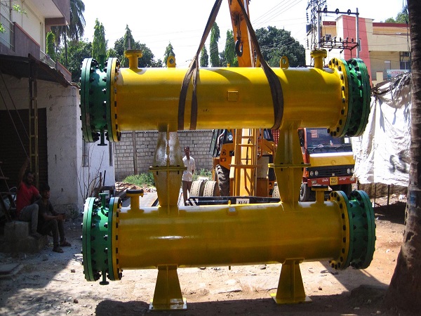
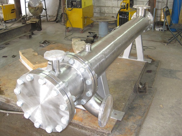
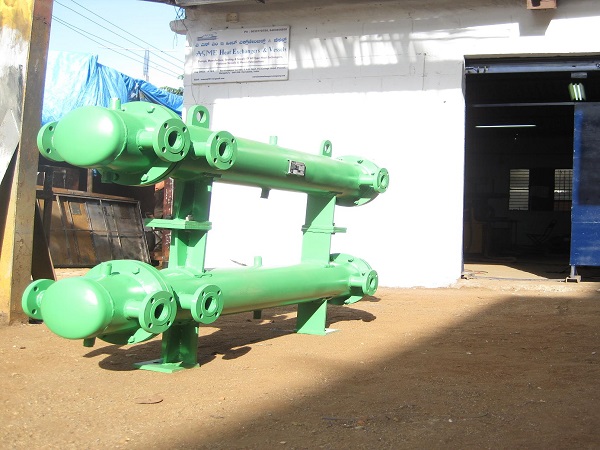
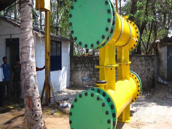
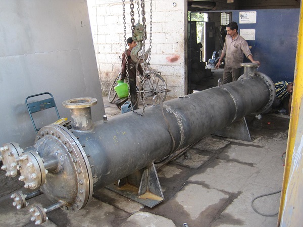
Shell and Tube Heat Exchanger is the most common type of heat exchanger in oil refineries and other large chemical processes, and is suited for higher-pressure applications. Shell Tubes Heat Exchanger are classified into fixed and Floating type Heat Exchangers . Fixed type Heat Exchangers are used where there are absolutely no chances for inter mixing of two fluids.
Shell and tube heat exchangers consist of a series of tubes. One set of these tubes contains the fluid that must be either heated or cooled. The second fluid runs over the tubes that are being heated or cooled so that it can either provide the heat or absorb the heat required.
In this type, the tube sheets are completely welded to the shell and acted as shell flanges. The Floating type Heat Exchangers has the advantages of removability of tube bundle and access for cleaning both inner and outer side of tubes and shell.
Specifications
- Shell Tube Heat Exchanger stream a process fluid and other cooling water or air.
- This is an efficient way to conserve energy.
- Two-phase heat exchangers can be used to heat a liquid to boil it into a gas.
Applications
- space heating
- refrigeration
- air conditioning
- power plants
- chemical plants
- petrochemical plants
- petroleum refineries
- natural gas processing
- sewage treatment
Advantages
- Shell Tube Heat Exchanger is often easy to service, particularly with models.

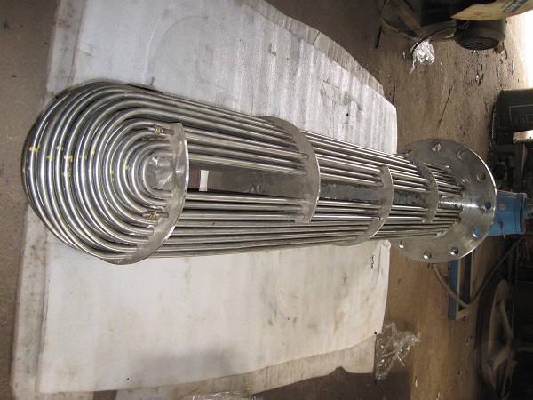
U Tube Bundle Heat Exchangers
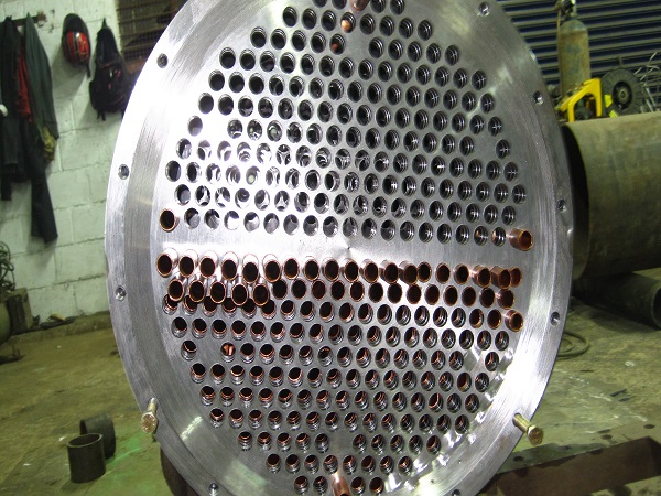
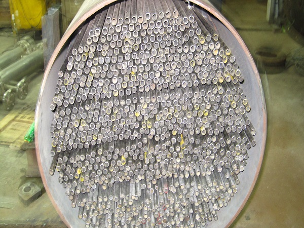
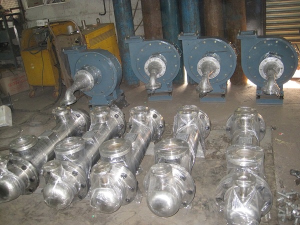
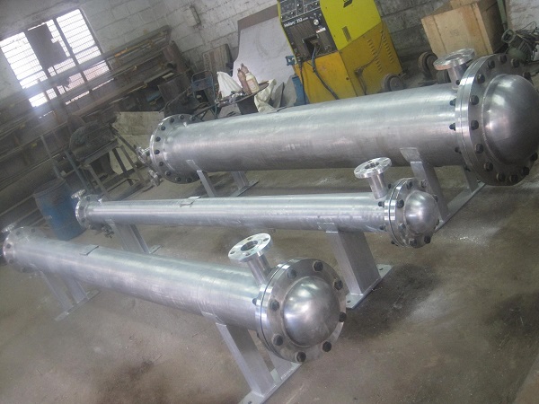
A heat-exchanger system consisting of a bundle of U tubes (hairpin tubes) surrounded by a shell (outer vessel); one fluid flows through the tubes, and the other fluid flows through the shell, around the tubes.Multitherm can duplicate any existing bundle to include dimensions, materials and performance. we can build "U" tube bundles, straight tube "floating" tube bundles, or we can retube fixed tubesheet heat exchangers when the bundles is not removable. multitherm is not locked into any one material. Most bundles tend to be build with copper tubes and steel tubesheets.
There can be many variations on the shell and tube design. Typically, the ends of each tube are connected to plenums (sometimes called water boxes) through holes in tubesheets. The tubes may be straight or bent in the shape of a U, called U-tubes.In nuclear power plants called pressurized water reactors, large heat exchangers called steam generators are two-phase, shell-and-tube heat exchangers which typically have U-tubes. They are used to boil water recycled from a surface condenser into steam to drive a turbine to produce power. Most shell-and-tube heat exchangers are either 1, 2, or 4 pass designs on the tube side. This refers to the number of times the fluid in the tubes passes through the fluid in the shell. In a single pass heat exchanger, the fluid goes in one end of each tube and out the other.Surface condensers in power plants are often 1-pass straight-tube heat exchangers (see Surface condenser for diagram). Two and four pass designs are common because the fluid can enter and exit on the same side. This makes construction much simpler.
There are often baffles directing flow through the shell side so the fluid does not take a short cut through the shell side leaving ineffective low flow volumes. These are generally attached to the tube bundle rather than the shell in order that the bundle is still removable for maintenance. Counter current heat exchangers are most efficient because they allow the highest log mean temperature difference between the hot and cold streams. Many companies however do not use single pass heat exchangers because they can break easily in addition to being more expensive to build. Often multiple heat exchangers can be used to simulate the counter current flow of a single large exchanger.
Specifications
- The simple design of a shell and tube heat exchanger makes it an ideal cooling solution for a wide variety of applications.
Applications
- One of the most common applications is the cooling of Hydraulic Fluid and oil in engines, transmissions and hydraulic power packs.
- With the right choice of materials they can also be used to cool or heat other mediums, such as swimming pool water or charge air.
Advantages
- One of the big advantages of using a shell and tube heat exchanger is that they are often easy to service, particularly with models where a floating tube bundle (where the tube plates are not welded to the outer shell) is available. Can also be used on fixed tube sheet heat exchangers.
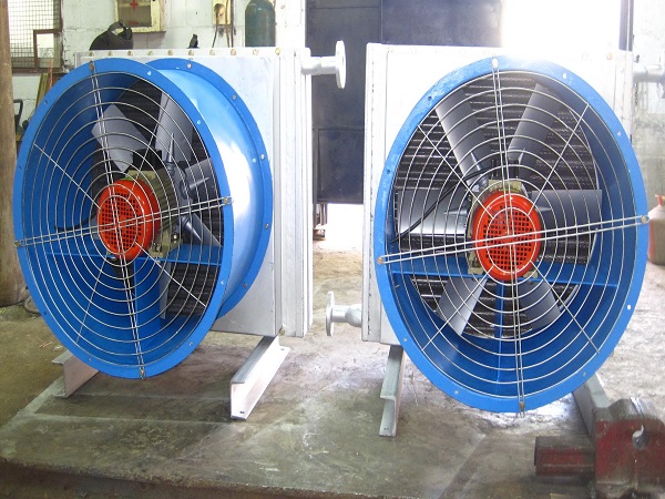
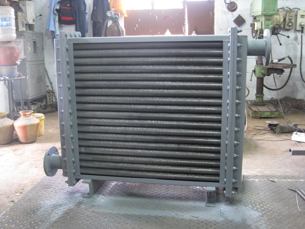
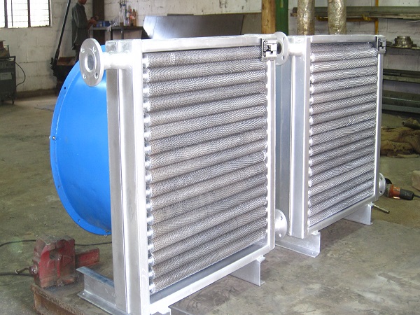
Air Cooled Heat Exchangers
Air-cooled heat exchangers are generally used where a process system generates heat which must be removed, but for which there is no local use. A good example is the radiator in your car. The engine components must be cooled to keep them from overheating due to friction and the combustion process. The excess heat is carried away by the water/glycol coolant mixture. A small amount of the excess heat may be used by the car's radiator to heat the interior. Most of the heat must be dissipated somehow. One of the simplest ways is to use the ambient air. Air-cooled heat exchangers (often simply called air-coolers) do not require any cooling water from a cooling tower. They are usually used when the outlet temperature is more than about 20 deg. F above the maximum expected ambient air temperature. They can be used with closer approach temperatures, but often become expensive compared to a combination of a cooling tower and a water-cooled exchanger.
Typically, an air-cooled exchanger for process use consists of a finned-tube bundle with rectangular box headers on both ends of the tubes. Cooling air is provided by one or more fans. Usually, the air blows upwards through a horizontal tube bundle. The fans can be either forced or induced draft, depending on whether the air is pushed or pulled through the tube bundle. The space between the fan(s) and the tube bundle is enclosed by a plenum chamber which directs the air. The whole assembly is usually mounted on legs or a piperack.
The fans are usually driven be electric motors through some type of speed reducer. The speed reducers are usually either V-belts, HTD drives, or right angle gears. The fan drive assembly is supported by a steel mechanical drive support system. They usually include a vibration switch on each fan to automatically shut down a fan which has become imbalanced for some reason.
The air-cooled heat exchangers are mostly used when the plant location and the ambient conditions do not allow an easy and economic use of other cooling systems.
Specifications
- Lower environmental impact than shell and tube heat exchangers thanks to the elimination of an auxiliary water supply.
Applications
- Reduction of maintenance costs.
- No problem arising from thermal and chemical pollution of cooling fluids.
Advantages
- Easy installation by bolted assembly.
- Flexibility for any plant location and plot plan arrangement(installation over other units)
Oil Coolers
Oil cooling refers to a process whereby heat is displaced from a 'hotter' object, into a cooler oil and is the principle behind oil cooler devices. The oil carrying the displaced heat usually passes through a cooling unit such as a radiator or less commonly a gas decompresser. The cooled oil repeats this cycle, to continuously remove heat from the object.An assembly for cooling oil in the lubrication system of an internal combustion engine. Oil coolers are installed mainly in motor vehicles, whose engines often operate under difficult thermal conditions. Oil coolers may be of the air-cooled or water-cooled type. The air-cooled oil cooler consists of brass tubing to which cooling fins are soldered. The oil circulated in the tubing by the oil pump is cooled by air when the vehicle is in motion. The oil cooler is connected to the lubrication system in parallel with the main oil pressure line. The cooled oil is returned to the crankcase of the engine.
We are proud to introduce ourselves as one of the leading Industrial Oil Cooler Manufacturers from India. We have outstanding information and communication technologies that have made us one of the top notch air Oil Cooler and engine oil cooler manufacturers in India. Our hi-tech plant and use of best quality raw materials help us to generate oil cooler that are industry benchmark of innovation and quality.
Specifications
- Oil cooler can be connected to through hoses to the high-performance blocks by removing the plugs above the oil filter pad.
- It also contributes to lowering the engine-temperature. Of the three engine cooling systems, oil cooling is the most promising for getting big cooling gains with relatively little effort. It is necessary to keep the temperature of the oil, needed for the functioning of the engine and its subsystems, under control. Too high temperatures lead to a rapid degradation of the oil's lubrication characteristics with the risk of damaging mechanical parts.
- They may be designed to exchange heat between oil and air rather than oil and the coolant in the engine cooling circuit.
- The latter involves simplified oil circuits and low costs if compared to the oil-air solutions, which offer higher performances and do not imply an additional thermal load for the radiator.
Applications
- An oil cooler is a separate, smaller radiator from an engine's main radiator, which maintains an oil supply at a consistent, optimal temperature.
- Broadly put, lower oil temperatures prolong the life of an engine or transmission.
- An oil cooler can play an important role in the smooth running of a vehicle by dissipating heat while transporting oil away from moving parts into the oil pan.
- The optimum temperature for oil is between 180 and 200 degrees Fahrenheit.
- Failures start to occur when oil cannot dissipate its collected heat fast enough and rises past this threshold.
- As it begins to break down, oil loses its lubricating, as well as its cooling, properties.
- While a majority of cars are not manufactured with proprietary engine oil coolers, there is a large aftermarket for them, and they are common accessories in vehicles involved in towing and other heavy-duty applications.
- Oil cooling kits exist for both motors and automatic transmissions.
- In engines, oil not only functions as a lubricant but also as the coolant for a number of parts.
- A motor's bottom end, which includes parts such as the crankshaft, bearings, camshaft, rods, and pistons, is cooled only by engine oil.
Advantages
- Oil has a higher boiling point than water, so it can be used to cool items 100°C or higher.
- Oil is an electrical insulator; thus, it can be used inside of or in direct contact with electrical components.
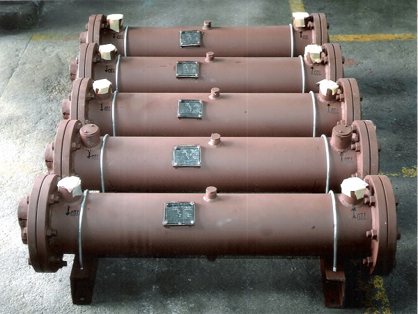
Condensers
Gland Vent/Surface Condensers
Gland vent/surface condensers, which are suited for condensation of gland vent in turbines. Surface condensers are commonly used for a water-cooled shell and tube heat exchanger. These are used in thermal power stations for the purpose of exhausting steam from a steam turbine. Our company manufactures customised range of surface condenser 1 ton to 4 ton capacity with various features that includes connection for repair, dais, reticulation nozzles, hot well & if connection, connections for instruments including level gauges, flash pipe with relevant connection and stand pipes with required connection.
Oil Systems
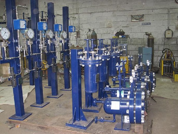
API Petrochemical Plant
Gland vent/surface condensers, which are suited for condensation of gland vent in turbines. Surface condensers are commonly used for a water-cooled shell and tube heat exchanger. These are used in thermal power stations for the purpose of exhausting steam from a steam turbine. Our company manufactures customised range of surface condenser 1 ton to 4 ton capacity with various features that includes connection for repair, dais, reticulation nozzles, hot well & if connection, connections for instruments including level gauges, flash pipe with relevant connection and stand pipes with required connection.
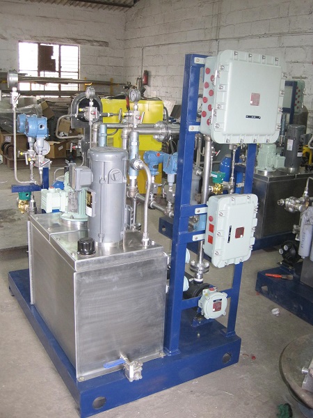
Lube Oil Systems
Lube Oil Consoles, Seal Oil Systems and Control Oil systems are designed to provide pressurized lubricating oil to various types of industrial rotating equipment. Typically, these lube oil systems include pumps, heat exchangers, filters, controls and instrumentation.
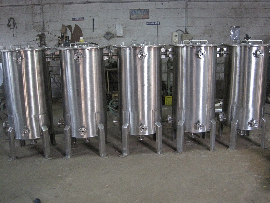
Tanks & Vessels
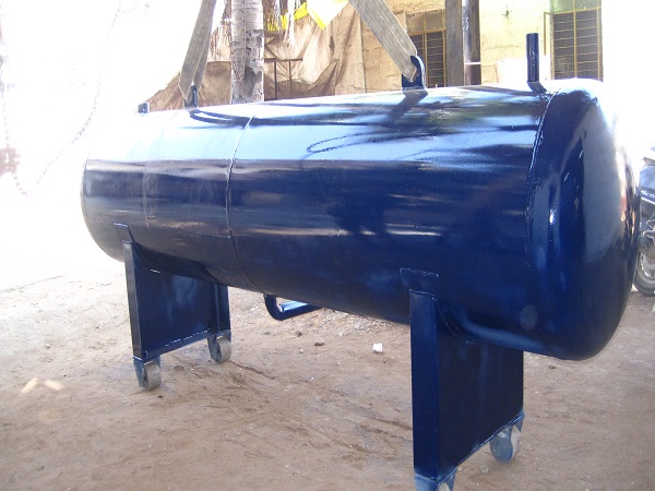
A pressure vessel is a closed container designed to hold gases or liquids at a pressure substantially different from the ambient pressure.
The pressure differential is dangerous and many fatal accidents have occurred in the history of pressure vessel development and operation. Consequently, pressure vessel design, manufacture, and operation are regulated by engineering authorities backed by legislation. For these reasons, the definition of a pressure vessel varies from country to country, but involves parameters such as maximum safe operating pressure and temperature.
More complicated shapes have historically been much harder to analyze for safe operation and are usually far more difficult to construct.
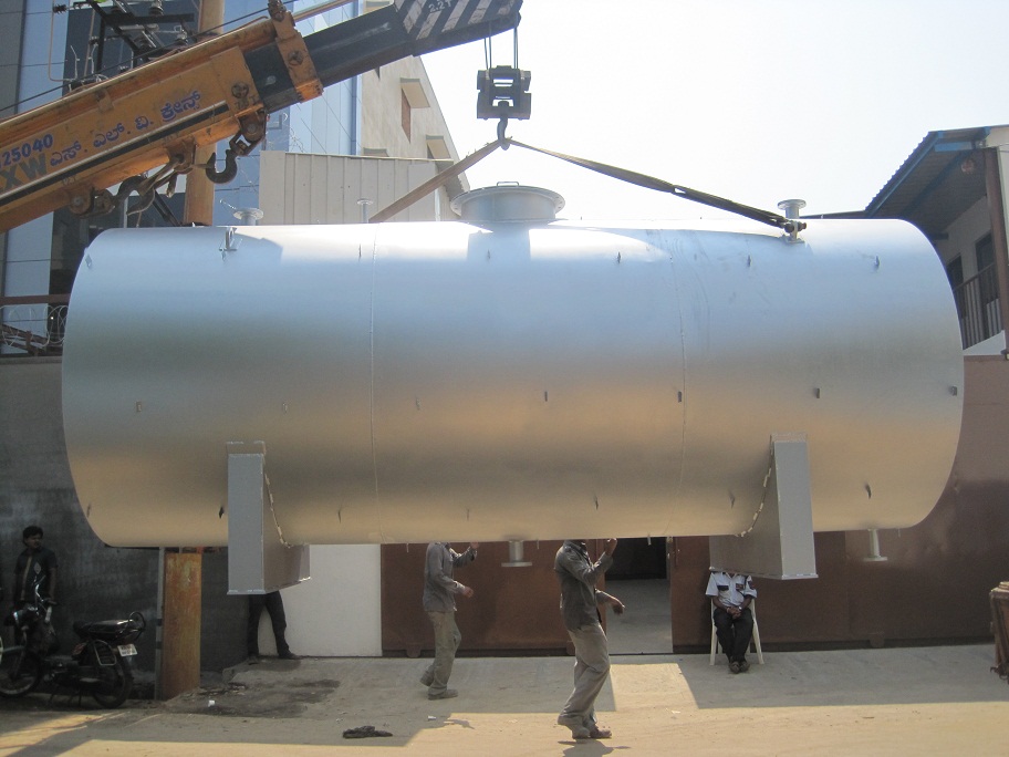
Theoretically, a spherical pressure vessel has approximately twice the strength of a cylindrical pressure vessel. However, a spherical shape is difficult to manufacture, and therefore more expensive, so most pressure vessels are cylindrical with 2:1 semi-elliptical heads or end caps on each end. Smaller pressure vessels are assembled from a pipe and two covers. A disadvantage of these vessels is that greater breadths are more expensive, so that for example the most economic shape of a 1,000 litres (35 cu ft), 250 bars (3,600 psi) pressure vessel might be a breadth of 914.4 millimetres (36 in) and a width of 1,701.8 millimetres (67 in) including the 2:1 semi-elliptical domed end caps.
Specifications
- Pressure vessels can theoretically be almost any shape, but shapes made of sections of spheres, cylinders, and cones are usually employed.
- A common design is a cylinder with end caps called heads. Head shapes are frequently either hemispherical or dished (torispherical).
Applications
- Pressure vessels are diving cylinders, recompression chambers, distillation towers, autoclaves, and many other vessels in mining operations, oil refineries and petrochemical plants, nuclear reactor vessels, submarine and space ship habitats, pneumatic reservoirs, hydraulic reservoirs under pressure, rail vehicle airbrake reservoirs, road vehicle airbrake reservoirs, and storage vessels for liquified gases such as ammonia, chlorine, propane, butane, and LPG.
Advantages
- Pressure vessels are used in a variety of applications in both industry and the private sector.
- They appear in these sectors as industrial compressed air receivers and domestic hot water storage tanks.